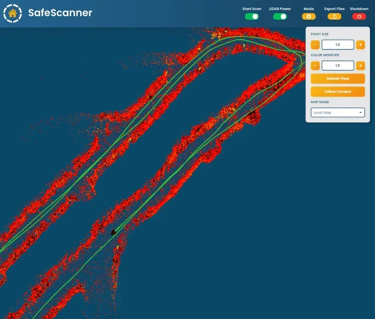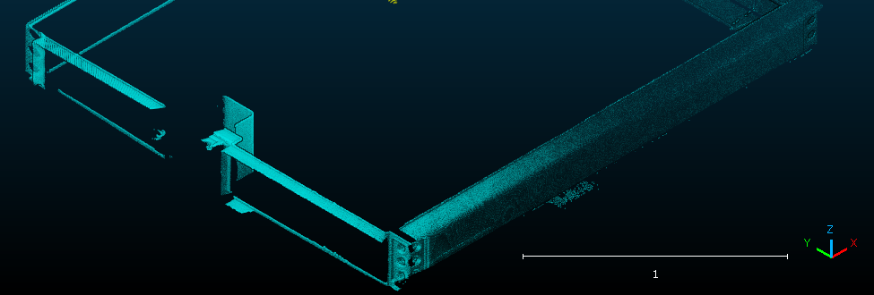
01 / ENVIRONMENT
Built for Real Mining Environments
SafeSight's inspection and measurement technologies are designed for demanding mining and underground environments, including active, deep, difficult-to-access and challenging shaft conditions.
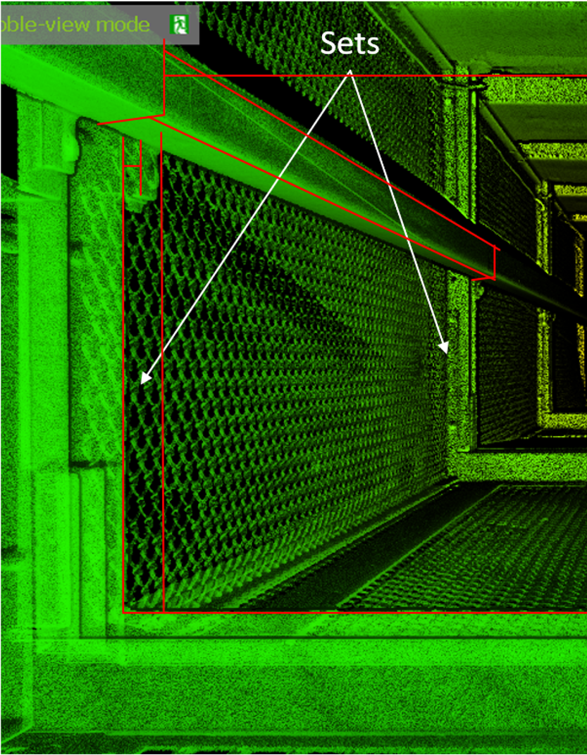
 FIELD INTELLIGENCE / ONLINE
SHAFT AVAILABILITY BRIEFING 01
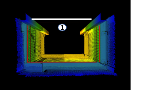
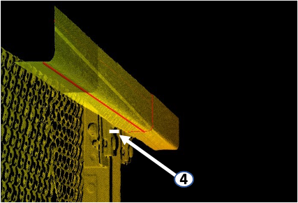
Capture detailed mine shaft information using LiDAR, 3D scanning, imaging, digital measurement and automated data processing—without relying solely on traditional manual inspection methods.
Underground Drone Flights
Client Safety Engagements
3D Models
Years of Expert Experience
02 Operating context / verified proof
01 / ENVIRONMENT
SafeSight's inspection and measurement technologies are designed for demanding mining and underground environments, including active, deep, difficult-to-access and challenging shaft conditions.
03 Cost exposure / operational story
Inspection cost is rarely one line item. It can accumulate across the work required, the access window consumed, the production affected and the information that must be measured again.
Not a single cost. A connected operating story.
Traditional shaft inspection activities can require specialized personnel, preparation and significant time to access and examine shaft infrastructure. Digital data capture can reduce the amount of manual work required to collect measurements and visual information.
When shaft inspection requires operational interruptions, the cost can extend beyond the inspection crew. Restricted shaft availability can affect hoisting, personnel movement, material movement and other underground activities.
A shaft is critical infrastructure. When inspection activities interfere with shaft availability, the resulting operational impact can be greater than the direct inspection cost. Digital inspection can help collect repeatable information with less operational disruption.
Manual measurements can be time-consuming and difficult to repeat consistently. Digital scanning and imaging create a detailed record that can be measured, reviewed and compared after the inspection.
05 Digital inspection / system stack
Each layer adds usable information to the shaft record—from remote capture to reporting for engineering, maintenance and planning workflows.
Select a layer to inspect the workflow06 Inspection record / progressive reuse
Five related activities, one evolving record. Select a stage to see how captured evidence becomes more structured and reusable.
CAPTURE → STRUCTURE → REUSEA record of what was seen
Evaluate shaft conditions using visual and spatial information captured through remote digital inspection technologies.
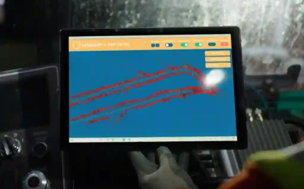 EVIDENCE / 01 — OBSERVE
07 Inspection scope / shaft blueprint
Select an area to review the information captured and documented as part of an inspection scope.
VISIBLE CONDITIONS ≠ DIAGNOSIS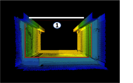 SPATIAL + VISUAL RECORD / SOURCE VIEW
08 Operational value / problem explorer
Explore the operational problems digital inspection may help address. The practical value depends on the shaft, scope, conditions and project requirements.
SELECT A PROBLEM TO REVEAL EVIDENCERemote digital data capture can reduce operational disruption associated with traditional inspection activities. Actual savings depend on the shaft and inspection scope.
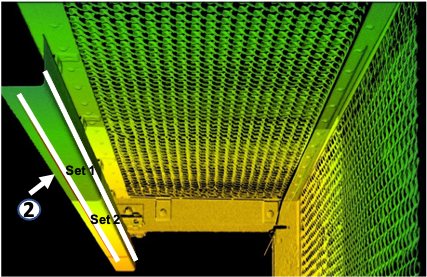 EVIDENCE VIEW / 01
Digital capture can reduce repetitive manual measurement and documentation activities.
High-resolution spatial data provides a detailed measurement record. Actual accuracy depends on equipment, conditions and project requirements.
Less disruptive inspection workflows may give mines greater flexibility to collect condition data more frequently.
Connect findings to measurements, images, CAD information and previous inspection records.
Digital inspection records can be revisited, measured and compared.
09 Operating model / workflow transition
Two operating models. Follow each lane to see how information is gathered before it converges into a reviewable record.
SELECT A LANE TO TRACE THE WORKFLOWSOURCE VIEW / 02INFORMATION RECEIVED
Digital informationLiDAR / IMAGING / 3D SCANNINGThe difference is not simply the technology; it is the type of information received. A digital workflow can provide a spatially connected dataset that can be measured, reviewed and compared.
10 Operational effects / outcome path explorer
Follow an evidence record into different operational contexts. The effect depends on the shaft, inspection scope, conditions and project requirements.
SELECT A PATH TO TRACE THE RECORDEarlier identification of changes can give maintenance teams more information to plan work before problems become unexpected interruptions.
EVIDENCE VIEW / 0111 Inspection planning / cadence planner
Inspection timing and scope depend on site conditions and applicable requirements.
EXPLORE THE PLANNING LOGICWHAT SHAPES THE DECISION
Factors can include shaft age and condition, depth and usage, environmental conditions, ground or seismic conditions, lining and construction, hoisting activity, previous damage or repairs and applicable requirements.
12 Decision support / evidence explorer
Six practical reasons. Select a lens to inspect the evidence, relevance and handoff.
SELECT A REASON TO OPEN THE RECORD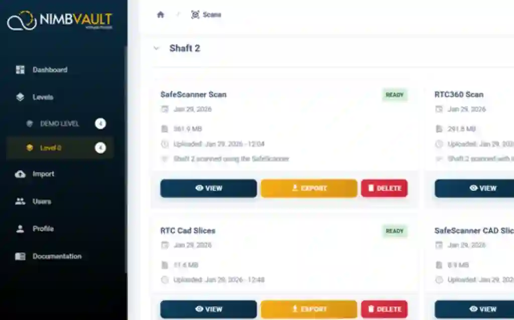 TRACK RECORD / 06
PUBLIC WEBSITE-REPORTED FIGURES
Public website-reported figures: 2,000+ underground drone flights, 70+ client safety engagements, 400+ 3D models and 25+ years of expert experience.




13 Results / evidence-led output record
Official output examples first. Project-level results appear only when the record supports publication.
SELECT A VIEW OR RESULT LENS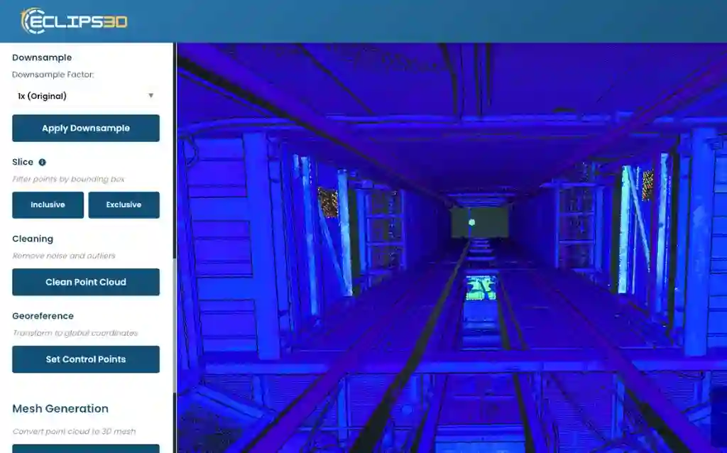
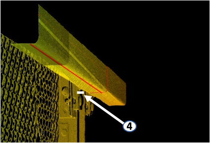
Authentic SafeSight output example. No named mine, customer or project is implied.
14 Field guide / questions answered
Mine shaft inspection is the process of evaluating shaft infrastructure and conditions through visual observation, measurement, scanning and other inspection methods.
Digital mine shaft inspection uses digital technologies to capture, measure, document and analyze shaft conditions, producing spatial data, 3D models, visual documentation, measurements and reports.
Automated mine shaft inspection refers to workflows where technology reduces or automates parts of data capture, measurement, processing or analysis. The level of automation depends on the technology and project scope.
SafeSight uses remote digital technologies including LiDAR-based scanning, imaging, photogrammetry and 360° video to capture shaft information. Captured data can be processed into 3D models, measurements, alignment reports and other outputs.
Yes. SafeSight's remote inspection approach is designed to capture shaft data without relying solely on personnel entering the shaft for inspection activities. The appropriate method depends on shaft configuration and conditions.
Depending on the project, measurements can include shaft dimensions, guide alignment, guide width and depth, clearances and other relevant spatial information.
Duration varies by shaft depth, scope, data requirements, access conditions and technology. A SafeSight assessment can determine an appropriate approach.
There is no single frequency for every shaft. Frequency depends on applicable requirements, shaft condition, operating conditions, previous findings and the mine's inspection program.
Depending on project requirements, SafeSight can provide 3D shaft models, 360° video, DXF measurements, alignment information and inspection findings.
Cost depends on shaft configuration, depth, scope, technology, data requirements and operating conditions. A SafeSight assessment is needed for project-specific cost.
16 / INITIAL SHAFT REVIEW
Talk through your shaft configuration, scope and data requirements with SafeSight.
Or email us directly at info@safesightxp.com